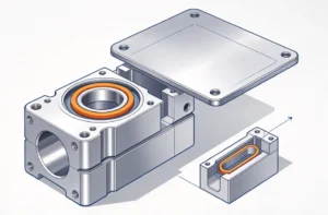
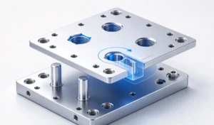
Dowel pin hole tolerance should be selected from the actual pin limits and the function of each hole. A removable plate needs clearance to slide over its locating pins; the base needs a defined method of retaining them.
If each hole accepts a pin individually but the plate will not seat over both pins, check the complete locating pattern. Hole spacing and axis alignment can prevent assembly even when the diameters are acceptable.
Choose dowel pin hole size for retention or removal
A press-fit dowel pin hole provides interference to retain a conventional solid pin in the base component. The removable mating component normally needs a clearance fit, often called a slip fit. Ground solid pins and spring pins have different retention mechanisms, so their hole recommendations should be evaluated separately.
Start with the selected pin’s drawing or specification. Confirm its diameter limits, material and intended installation. Then choose the hole limits for the required retention, removal and locating accuracy. A fit used in a thick steel block may be unsuitable for a thin aluminum wall.
H7 alone does not define the assembled fit
In the ISO limits and fits system, an H7 callout describes the hole tolerance zone. Select the pin tolerance separately to establish the assembled fit. Depending on the selected pin tolerance, the combination can produce clearance, transition or interference.
Ganter, for example, specifies an m6 diameter tolerance for its DIN 7979 dowels and describes an H7 mating hole as a transition fit.
For a cylindrical hole and pin, check the limiting diametral clearance:
- Minimum clearance = smallest hole − largest pin.
- Maximum clearance = largest hole − smallest pin.
If both results are positive, the size limits provide clearance. If both are negative, they provide interference. If the range spans positive and negative values, assembly can vary between clearance and interference. A zero result is a line-to-line condition and provides no positive clearance at that limit.
These calculations describe size fit. Account for geometric accuracy, surface condition and the assembly environment when setting the final limits.
Worked fit example: 8 mm H7/m6
For a nominal 8 mm diameter, Ganter’s DIN ISO 286-2 extract gives these limits:
| Feature | Diameter limits |
|---|---|
| H7 hole | 8.000–8.015 mm |
| m6 pin | 8.006–8.015 mm |
- Minimum diametral clearance: 8.000 − 8.015 = −0.015 mm.
- Maximum diametral clearance: 8.015 − 8.006 = +0.009 mm.
The range permits up to 15 μm of interference or 9 μm of clearance. This is a transition fit, so it does not guarantee positive clearance for a removable plate. Look up the limits for the actual nominal diameter and selected tolerance classes.
Why two slip-fit holes can still bind
Two close-fitting round pins each restrict movement in two directions within the mating plane. The assembly must accommodate the difference between the pin pattern and the hole pattern while maintaining the required location.
The center-distance mismatch must fit within the combined radial clearances. Diametral clearance and radial clearance are different quantities: for a round hole and pin, radial clearance is half the diameter difference.
A simplified two-pin example
For a separate geometric example, assume the following dimensions in millimeters. These hypothetical values are independent of the H7/m6 limits above:
- Both pin diameters: 8.000 mm.
- Both mating-hole diameters: 8.020 mm.
- Distance between pin centers: 50.000 mm.
- Distance between hole centers: 50.040 mm.
Each hole has 0.020 mm of diametral clearance, giving 0.010 mm of radial clearance around its pin. With the removable plate free to shift, the two clearances together can accommodate up to 0.020 mm of center-distance difference in this ideal geometry.
The actual spacing difference is 50.040 − 50.000 = 0.040 mm. It exceeds that allowance, so the two-pin pattern cannot engage without deformation even though either pin fits either hole on its own.

This example assumes perfectly round holes, straight parallel pins and axes perpendicular to the mating faces. It is a geometric illustration, not a recommended tolerance scheme. Actual parts also require checks for form error, axis orientation, engagement length and temperature.
For interchangeable parts, evaluate the permitted size and position variation in both components. Check the limiting combinations across their tolerance ranges, rather than accepting a fit between one selected pair.
Use a locating arrangement that accommodates the pattern
One round locating pin paired with a diamond locating pin is an established fixture arrangement. The round pin locates in two in-plane directions. The relieved diamond pin provides the secondary locating constraint without duplicating both directions.
Carr Lane describes this pairing for locating from two machined holes or aligning fixture components. Use the chosen locator’s installation guidance to define its orientation, head clearance and mounting requirements.
A round hole paired with an appropriately oriented slot is another option. For a simple two-locator layout, the slot can accommodate spacing variation along the line joining the locators while its width controls the transverse direction. The design must still satisfy the application’s locating and load requirements.
Evaluate dowel pin hole tolerance and hole-spacing variation together. Consider a relieved secondary locator for repeated plate removal, especially when spacing variation would cause two round pins to bind. If an existing interface requires two round pins, verify assembly through the complete tolerance analysis.

Increasing both hole diameters also increases the available locating movement. Check the repeatability requirement before using added clearance to resolve binding.
For approved plate or block designs, see Baosheng’s CNC milling services.
Have a locating plate ready to quote? Request a CNC machining quote with the CAD model, drawing, pin specification and mating-part information. Identify whether the order covers one component or both sides of the joint.
Diagnose the cause before changing the hole size
Begin with the symptom. Record actual pin diameters, finished hole sizes and the condition in which the assembly fails.
One pin will not enter one hole
Check diameter limits, the hole entrance, burrs and bore condition. For a blind hole, also check usable hole depth, pin projection and whether trapped air needs a venting provision. Some dowels include extraction threads and venting flats for blind-hole use.
Specify the required entry chamfer and usable engagement length on the drawing. A drilled hole’s overall depth does not necessarily equal the length of full-diameter bore available to the pin.
Each pin fits separately, but both will not engage
Measure the center distance and the pattern’s relationship to the functional datums. Check the pin and hole axes through the engagement depth, and verify that the mating faces can seat in the intended orientation.
Reaming is commonly used to finish dowel holes, but it depends on the quality of the pre-machined hole. SPIROL’s hole-preparation guidance cautions that a reamer will not correct a crooked or otherwise poor-quality starting hole.
Define the finished size, position and other geometric requirements on the drawing. Verify the starting-hole location before reaming.
The fit becomes tight after finishing
Anodizing can change an aluminum hole’s finished size. Review coating buildup, pretreatment and the agreed masking or post-finish machining sequence. Establish whether acceptance applies before or after the finish.
Our article on 6061 aluminum fit changes after anodizing explains this separate finishing issue. Avoid removing coating as an informal assembly fix when that coating is part of the specification.
Put fit, position and acceptance on the CNC drawing
On the CNC drawing, list the selected pin limits and mating pattern. Mark retention holes and removable locating holes separately.
The machining package should include:
- Finished hole limits or tolerance classes, with the corresponding pin limits.
- Through-hole or blind-hole identification, usable depth and entry details.
- Functional datums and the required location and orientation controls.
- The mating pattern, locating arrangement and required assembled pin projection.
- Material grade, heat treatment or finish, masking and acceptance condition.
- Quantity, drawing revisions and the inspection records required.
Size, position and assembly checks answer different questions. A diameter check does not verify a two-hole pattern. Where position is critical, agree on the datum setup and an appropriate measurement method, such as a coordinate measuring machine (CMM).
If a functional mating gauge or assembly check is required, define the reference part or gauge and its acceptance criteria. State whether parts must be interchangeable or supplied as identified matched sets. Include that inspection scope in the quotation.
For a removable plate requiring interchangeability, a drawing note could read:
Hole limits apply after the specified finish. Supply interchangeable plates. Inspect the locating-hole pattern to the datum reference frame on this drawing. Refer to the assembly drawing for the mating-pin specification.
Adapt this note to the design. It supplements the specified dimensions and geometric tolerances; the note alone does not establish an acceptable fit.
Use our CAD and drawing checklist for CNC quotes to prepare the file package.
Set dowel pin hole tolerance using the actual pin limits and the complete mating pattern. For custom locating plates, adapter blocks or other CNC parts, send your drawings to Baosheng for a quote. Include the mating-part information needed to evaluate the specified machining scope.