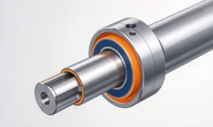
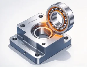
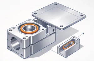
Select bearing housing bore tolerance based on the bearing type, outer-ring load, housing construction, and required axial movement. H7 is a common option for certain stationary outer-ring load conditions, but it is not a universal specification for every bearing housing.
A machining drawing also needs to define seat geometry and inspection conditions. A diameter reading within limits does not establish that the bearing will seat squarely or that the housing will retain its shape after assembly.
This guide covers CNC-machined housings, end covers, and support blocks with cylindrical seats for rolling-bearing outer rings.
1. Select the Housing Fit for the Outer-Ring Load
Start with the bearing manufacturer’s part number, tolerance class, and fit recommendations. The housing bore mates with the bearing’s outside diameter (OD). The shaft mates with the inner-ring bore; these are separate interfaces. Choose the required clearance, transition, or interference fit at each interface before selecting a tolerance class.
When Is an H7 Bearing Housing Fit Appropriate?
JTEKT’s general radial-bearing recommendations include H7 for a stationary outer-ring load where axial displacement of the outer ring is permitted. That table applies to steel or cast-iron housings. Its conditions should be checked before transferring the recommendation to another housing.
A stationary load means the loaded zone stays in the same position relative to the ring. If that zone moves around the outer ring, the ring experiences a rotating load even if the housing itself does not rotate.
A rotating load can cause a loosely fitted ring to creep circumferentially on its seat. An interference fit is generally needed for the ring carrying that load. Variable loads, shock, and vibration also require application-specific review.
Account for Material, Temperature, and Axial Movement
Before selecting the bearing housing fit, establish:
- Whether the outer ring carries a stationary, rotating, or indeterminate load.
- Whether the housing is solid or split, and how much material surrounds the seat.
- Whether the outer ring must slide axially to accommodate the bearing arrangement.
- The housing material, operating temperatures, and mounting method.
Aluminum and thin-wall housings should not automatically inherit a fit selected for a rigid steel housing. Material stiffness, thermal expansion, and seat construction affect the installed fit.
Where axial movement is required at the outer-ring seat, an interference fit can prevent it. A transition fit also cannot guarantee sliding because some permitted combinations produce interference. Some bearing arrangements accommodate movement within the bearing instead. Resolve that function before selecting the fit.
For a split housing, review the joint construction and the bearing manufacturer’s specific recommendation before increasing interference. For applications requiring high running accuracy, specify the bearing accuracy class and seat geometry. Additional interference cannot correct an out-of-round seat.
2. Calculate Clearance Using the Bearing OD Tolerance
H7 defines a housing size tolerance; it does not supply the bearing’s OD limits. Calculate the resulting fit from both mating components.
For a dimensional clearance calculation:
Minimum clearance = smallest housing bore − largest bearing OD
Maximum clearance = largest housing bore − smallest bearing OD
A positive result represents clearance; a negative result represents interference. If the permitted range crosses zero, it is a transition fit. These are diametral size differences, not radial bearing internal clearance.
Worked Example: A 62 mm H7 Housing Seat
Consider a nominal 62 mm radial ball bearing with Normal OD tolerances. SKF’s housing-fit table gives the following limits for the range over 50 mm up to and including 80 mm:
| Component | Size limits |
|---|---|
| Housing bore, 62 mm H7 | 62.000–62.030 mm |
| Bearing mean OD, Normal tolerance | 61.987–62.000 mm |
The theoretical clearance limits are:
- Minimum: 62.000 − 62.000 = 0.000 mm.
- Maximum: 62.030 − 61.987 = 0.043 mm, or 43 µm.
This is a clearance fit with a theoretical minimum of zero. The 30 µm housing tolerance combines with the bearing’s 13 µm mean-OD tolerance to produce a larger theoretical fit range.
The 62 mm nominal size is an illustrative selection. The limits come from the manufacturer’s table, not a measured Baosheng part. This example applies to the stated bearing tolerance family; tapered roller bearings, thrust bearings, or special accuracy classes require their own data.
Compare H7, H6, and J7 Using the Same Bearing
For the same 62 mm bearing and OD limits, the theoretical results are:
| Housing class | Resulting diametral fit |
|---|---|
| H7 | 0 to 43 µm clearance |
| H6 | 0 to 32 µm clearance |
| J7 | 12 µm interference to 31 µm clearance |
NTN’s Class 0 radial-bearing fit table gives these same resultant ranges for the applicable diameter band. H6 narrows the clearance range relative to H7. J7 is a transition fit in this example. Its classification follows the two components’ limits, not the housing letter alone.
SKF also lists probable fits, separately from theoretical extremes. A probable range is a statistical estimate, not a guarantee that all permitted size combinations fall within it. Use the theoretical extremes to evaluate limiting assemblies. Any statistical acceptance approach needs an agreed method and production data.
Keep Housing Clearance Separate from Internal Clearance
The calculated gap is between the outer ring and its seat. Bearing internal clearance is the relative movement available between the bearing rings and rolling elements.
Interference can deform a mounted ring and reduce internal clearance. Operating temperatures can change it further. Making a housing tighter therefore requires a check of the mounted bearing condition, not just installation force.
3. Define Seat Geometry, Shoulders, and Surface Finish
A complete bearing housing bore tolerance specification should distinguish diameter limits from the geometry needed to support and locate the bearing.
Roundness, Cylindricity, and Bore Alignment
Identify the required roundness or cylindrical-form control, along with any relationship to another bearing seat or mounting datum. A few diameter measurements cannot establish every form or alignment requirement.
For two seats supporting one shaft, define their required axis relationship through the drawing’s datum system. Select the control and value for the bearing arrangement. Apply the governing drawing standard, including any envelope requirement; do not assume all standards interpret a size callout identically.
Shoulder Contact and Corner Clearance
The abutment shoulder must support the intended bearing-ring face. Specify its location and the required orientation or runout relative to the seat.
Check the bearing manufacturer’s mounting dimensions for shoulder diameter and permissible corner radius. An oversized housing fillet can interfere with the bearing corner and prevent full shoulder contact. Define the entry chamfer separately from the shoulder fillet, and remove burrs without altering the seat.

Bearing Seat Surface Finish
Specify bearing-seat surface finish using the required roughness parameter and units. Match the value to the bearing accuracy, fit, size, and service conditions. A universal Ra value should not replace the manufacturer’s guidance.
NTN distinguishes apparent interference, calculated from mating diameters, from effective interference after assembly. Surface asperities can flatten during fitting, reducing the effective interference. NTN’s published shaft-finish corrections should not be applied directly to a housing bore.
State whether the bore is masked, coated, or finished after surface treatment. The acceptance limits must describe the delivered condition. For aluminum parts, our guide to fit changes after anodizing explains why this needs to be resolved before machining.
Get a machining quote for your bearing housing or end cover.
Send CAD and drawings for a CNC quote, including the bearing designation, material grade, seat requirements, finish, and quantity.
4. Define the Inspection Condition Before Production
Agree on how the bearing seat will be supported and measured. This is especially relevant to thin-wall components, split housings, and covers secured by several bolts.
NSK warns in its super-precision bearing guidance that uneven retaining-cover bolt forces can increase outer-ring out-of-roundness. That is a reason to review assembly loading, rather than treating the loose component’s size report as proof of the installed condition.
Separate Released-Part and Restrained-State Checks
A released-part check measures the component after removal from machining workholding, using agreed support. If the drawing requires a restrained or assembled condition, specify the mounting fixture, mating components, fastener sequence, and tightening condition.
Where accessible, inspect the empty bearing seat with the specified housing joints or caps assembled before installing the bearing. If that condition differs from the delivery inspection, identify the additional check explicitly.
Do not change a bore’s nominal size to compensate for assembly distortion until the loading condition and resulting geometry have been established.

Request Records That Match the Requirement
Use the following to define the inspection scope:
| Requirement | Evidence to request |
|---|---|
| Bore size | Measurements at agreed axial positions and orientations |
| Roundness or cylindrical form | Results from a method suitable for the specified control |
| Seat-to-datum relationship | Geometric inspection using the drawing’s datum references |
| Finished condition | Confirmation of masking, treatment, and final inspection stage |
| Restrained condition, if specified | Fixture and assembly condition recorded with the results |
Schaeffler’s mounting guidance calls for dimensional and geometric checks of bearing seats and measurement at multiple locations. It also specifies that the measuring equipment and components should be at approximately the same temperature.
An internal micrometer or calibrated comparator gauge can provide bore-size measurements. A sampling plan for size does not automatically verify full cylindricity. Agree on the instrument, access, and measurement method for each specified characteristic.
An Inspection Brief for the RFQ
The following is illustrative quotation language, to be completed by the approved drawing and inspection plan:
Supply the housing only, to the bearing-seat limits and datum requirements on the released drawing. Report bore size at the agreed entry, middle, and shoulder-end locations, with measurement orientations identified.
Identify the finished surface condition and inspection support. Where restrained-state inspection is specified, record the approved fixture, mating parts, fastener sequence, and tightening condition with the results.
This brief gives the supplier an inspection scope to quote. It does not replace numerical geometry limits, a complete drawing, or validation of the operating bearing assembly.
5. Prepare the Bearing Housing Drawing and RFQ
For CNC-machined blocks and housings, review our CNC milling services alongside the part geometry. Bore access, wall thickness, and the relationship between seats affect the machining and inspection plan.
A quotation package should include:
- STEP model and a dimensioned drawing with revision.
- Bearing manufacturer, designation, accuracy class, and applicable fit reference.
- Approved bore limits, geometric controls, shoulder details, and functional datums.
- Material grade, heat treatment, surface treatment, and final-condition requirements.
- Prototype or production quantity, inspection records, and any assembly-check scope.
Our CAD and drawing checklist for CNC quotes can help organize the files.
Keep bearing selection and operating validation with the responsible design team. A housing machining quote should clearly state whether it includes only the component or any agreed assembly work.
Specify bearing housing bore tolerance together with the bearing’s OD limits, operating requirements, seat geometry, and inspection condition. Request a quote for your bearing housing drawings with those requirements defined so the machining scope can be evaluated accurately.