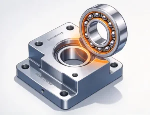
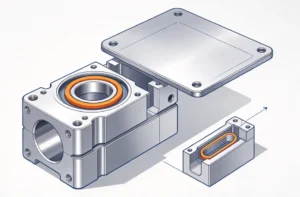
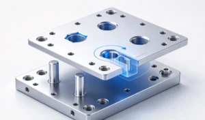
An O-ring groove can pass dimensional inspection while the assembled joint has too little seal compression. O-ring groove design must account for the distance from the groove bottom to the mating face, including any local assembly gap. Groove width also needs to leave room for the elastomer to deform and change volume in service.
This guide covers static axial, or face, seals in CNC-machined metal covers, housings, and flanges. Start with the correct gland type and seal size, calculate compression and available volume, then define the finished dimensions for machining.
1. Select the Gland Type, O-Ring Size, and Pressure Direction
A face seal compresses an O-ring between a groove in one component and a mating face. The gland is the assembled space that contains the seal.
Use the Correct Groove Design Chart
Select the chart by sealing arrangement before choosing O-ring groove dimensions:
| Arrangement | Design distinction |
|---|---|
| Static face or flange seal | Axial compression between a grooved face and a mating face |
| Static radial seal | Radial compression between a bore and an inserted component |
| Dynamic rod or piston seal | Sliding contact requires motion-specific squeeze, finish, and clearance guidance |
Use a separate chart for radial, dynamic, or dovetail grooves.
Record the O-ring’s size designation, inside diameter (ID), cross-sectional diameter, compound, and hardness. Include the dimensional tolerances.
Record the fluid, temperature range, and pressure differential. Match these inputs to the manufacturer’s face-seal chart, including its units and liquid or gas service assumptions.
Choose a Cross-Section That Fits the Tolerance Budget
A smaller cross-section uses less space but makes a given gland-height variation a larger percentage of the seal size. A larger section needs a wider and deeper groove, which must fit within the available sealing land and wall thickness.
For illustration, a 0.10 mm increase in gland height reduces squeeze by 5 percentage points for a 2.00 mm cross-section and 2.5 points for a 4.00 mm cross-section. This comparison assumes fixed cross-sections and illustrates geometric sensitivity, not recommended seal sizes.
Position the Ring for the Pressure Direction
For a circular face seal, pressure direction affects where the O-ring seats:
- Internal pressure pushes the ring outward. The groove’s outer wall supports the seal. Specify the groove’s outside diameter (OD) and width.
- External pressure, including atmospheric pressure around an evacuated cavity, pushes the ring inward. The inner wall supports the seal, making the groove’s inside diameter important.
Check the manufacturer’s installed stretch or outside-diameter interference requirement as well as the groove diameter. An external-pressure arrangement may stretch the ring over the inner wall; an internal-pressure arrangement may use slight OD interference to seat it at the outer wall.
If pressure reverses, review both conditions. A groove positioned for one direction should not be assumed suitable for the other.
For a circular face groove, w = (groove OD − groove ID) ÷ 2 is the radial width of the groove. Its depth is measured axially from the sealing land.
A rounded rectangular seal path also needs a compatible ring or molded seal and suitable corner geometry. A circular groove diameter alone cannot define that arrangement.
2. Calculate O-Ring Squeeze and Groove Depth
O-ring squeeze, also called O-ring compression, is the reduction in the seal’s cross-sectional height during assembly. For this face-seal calculation, define:
- d: O-ring cross-sectional diameter before axial compression, adjusted for installed stretch where applicable.
- t: machined groove depth measured from the finished sealing land.
- g: local separation between that land and the mating face after assembly.
- H: assembled gland height, equal to t + g.
All lengths must use the same units. Calculate compression as:
Squeeze (%) = (d − H) ÷ d × 100
When the mating face contacts the sealing land, g is zero and H equals groove depth. A joint with a spacer, incomplete seating, or local cover deflection needs a gap allowance. Assess that gap under the relevant assembly and operating conditions.
For a selected squeeze fraction s, rearrange the equation to estimate groove depth: t = d(1 − s) − g. Use 0.25 for 25% squeeze. Check the resulting depth across the ring and assembly tolerances.
Marco’s general design guidance lists 20–30% squeeze for face seals. Treat this as a starting reference. The selected cross-section, compound, application, and supplier’s specific gland chart govern the acceptable range.
A Tolerance Example: The Same Groove, Two Assembly Conditions
The following hypothetical example uses assumed tolerances, not standard limits or recommended production dimensions. Assume no installed stretch:
| Input | Assumed value |
|---|---|
| O-ring cross-section, d | 3.20 mm; limits 3.12–3.28 mm |
| Groove depth, t | 2.40 mm; limits 2.35–2.45 mm |
| Local assembled gap, g | 0–0.08 mm |
Nominal squeeze with direct face contact is:
(3.20 − 2.40) ÷ 3.20 × 100 = 25.0%
Now compare the limiting combinations:
- Minimum squeeze with direct contact: use the smallest ring and deepest groove. (3.12 − 2.45) ÷ 3.12 × 100 = 21.5%.
- Minimum squeeze with the maximum gap: gland height becomes 2.45 + 0.08 = 2.53 mm. (3.12 − 2.53) ÷ 3.12 × 100 = 18.9%.
- Maximum squeeze: use the largest ring, shallowest groove, and zero gap. (3.28 − 2.35) ÷ 3.28 × 100 = 28.4%.

The 0.08 mm gap changes minimum compression even though the machined groove stays within its specified limits. Compare the minimum and maximum squeeze with the chosen seal’s requirements.
Check Low Squeeze and Extrusion Separately
If minimum squeeze is insufficient, evaluate the assembled gap, ring size, and groove-depth limits together. Cover stiffness, fastener spacing, and the joint’s load path may need engineering review if they permit local separation.
A shallower groove can recover compression, but it also increases maximum squeeze and gland fill. It does not eliminate an extrusion gap. Pressure, clearance, temperature, and elastomer hardness must be checked separately for extrusion risk.
Where the seal design requires a backup ring, it provides support against extrusion at the clearance gap. Include its occupied volume in the groove-width review. Its material, dimensions, and position require application-specific selection; adding one is not a substitute for correcting an unintended opening in a face joint.
3. Check Gland Fill Before Finalizing Groove Width
O-ring gland fill is the percentage of available gland volume occupied by the seal:
Gland fill (%) = O-ring volume ÷ available gland volume × 100
Parker’s O-Ring Handbook gives 60–85% as guidance for most applications, with 75% as a nominal target. These figures allow space for dimensional variation, thermal expansion, and fluid-induced swelling. They are application guidance, not a universal acceptance limit for every compound or gland.
Estimate Groove Width from the Target Fill
For an unstretched ring in a rectangular gland without backup rings, a preliminary area calculation is possible when their effective mean perimeters are equal:
Gland fill (%) ≈ πd² ÷ (4wH) × 100
Here, w is groove width and H is assembled gland height. This approximation ignores corner fillets and other changes to the available volume. Use actual ring and gland volumes when those assumptions do not hold.
To estimate width for a chosen fill fraction f, rearrange the approximation:
w ≈ πd² ÷ (4Hf)
Using the hypothetical 3.20 mm cross-section, 2.40 mm gland height, and f = 0.75 gives a candidate width of approximately 4.47 mm. This is a nominal estimate before checking tolerances, fillets, or material volume changes.
For the worked tolerance check, assume a width of 4.60 mm, with limits of 4.50–4.70 mm.
At nominal dimensions and zero gap:
π × 3.20² ÷ (4 × 4.60 × 2.40) × 100 ≈ 72.8%
For maximum fill, use the largest ring, narrowest groove, shallowest depth, and zero gap. The approximation gives 79.9%. Check this value against the application’s fill limit after allowing for service-related volume changes.

Include Stretch, Swelling, and Actual Groove Geometry
Installed stretch can reduce the O-ring’s cross-section. Use the supplier’s correction method when recalculating squeeze, and use consistent installed geometry for the volume check.
Groove-bottom fillets reduce available gland volume. Fluid exposure and temperature can change seal volume, so a satisfactory nominal fill calculation does not establish an adequate expansion allowance.
O-ring groove design requires separate checks for minimum squeeze, maximum squeeze, and maximum fill. Increasing depth reduces fill but also reduces compression. Increasing width reduces fill without directly changing axial gland height.
Use the appropriate liquid or vacuum/gas groove-width guidance; the required widths may differ.
For a cooling assembly, review the seal interface alongside the channel layout and cover requirements in our cold plate CNC machining guide.
Get a quote for your grooved cover or housing.
Submit CAD and drawings for a CNC quote, including the material grade, finish, quantity, and selected O-ring specification. Mark the critical sealing surfaces on the drawing.
4. Specify Groove Geometry and Sealing Surfaces for CNC Machining
Once the seal and assembly checks are complete, translate them into measurable requirements. For milled covers and housings, our CNC milling services provide a relevant starting point for a drawing-based quotation.
Control Dimensions from the Finished Sealing Land
Specify the O-ring groove dimensions: width, depth, path or diameters, and location datum references. Identify the finished sealing land from which depth is measured. Define the mating face’s relevant flatness or profile requirements separately.
If anodizing, coating, or subsequent machining affects the interface, state which dimensions and surface requirements apply after those operations. An inspection made before finishing may not represent the delivered gland geometry.
Keep the component requirement and assembly assumption distinct. A groove-depth measurement on a loose cover does not establish the gap after that cover is bolted to a housing.
Distinguish Corner Radii from Edge Breaks
A plan-view corner radius describes the turn in the seal path. A groove-bottom fillet describes the cross-section where the wall meets the floor. Both affect the design, but they serve different purposes.
Specify both radii using the selected seal guidance. Define permissible edge breaks and inspect the edges the O-ring passes over during installation. A burr or sharp edge can cut the elastomer before assembly.
Deburr the part without altering the sealing land or groove dimensions.
A dovetail groove adds seal retention but has different geometry and machining requirements. Select it when retention is needed; use its own design guidance and volume calculation.

Specify O-Ring Groove Surface Finish
Mark the functional sealing surfaces and state the required roughness parameter and units. Ra, Rz, and RMS roughness (Rq) describe different measurements and should not be substituted numerically.
As reference points, Parker’s general static-seal guidance uses 32 microinches RMS, with 16 microinches RMS recommended for face-type gas seals. These convert to approximately 0.81 µm Rq and 0.41 µm Rq, respectively. Confirm the applicable seal chart; these values are not equivalent to Ra limits.
Inspect for burrs, dents, and scratches, particularly defects crossing the sealing contact path. A roughness measurement that meets its limit does not rule out a local leak path.
5. Resolve Assembly Risks Before Releasing the Machining Order
Use the observed symptom to choose the next check:
| Symptom | Check before changing the groove |
|---|---|
| Leakage immediately after assembly | Ring identity, local gland height, seating, and surface damage |
| Cuts or pinched areas on the removed ring | Installation edges, ring placement, and available gland volume |
| Leakage under pressure | Joint separation, extrusion clearance, and the seal’s pressure/temperature guidance |
| Leakage after fluid exposure or heating | Compound compatibility, volume change, and the gland’s expansion allowance |
These checks identify possible causes; the symptom alone does not establish a diagnosis.
For the machining order, supply:
- The approved O-ring size, compound designation, and supplier reference.
- Groove dimensions, tolerances, radii, and location datums.
- Sealing-land and mating-face requirements in the finished condition.
- Material grade, finish, drawing revision, and production quantity.
- Required dimensional records and any agreed testing scope.
Use our CAD and drawing checklist for CNC quotes to assemble the files.
Machining to the drawing and validating the assembled seal are separate acceptance tasks. If leak testing is required, agree on the assembly scope, test medium, pressure differential, temperature, duration, and acceptance criterion. Component dimensional inspection alone cannot prove assembly leak performance.
Effective O-ring groove design connects the seal specification, assembled gap, available gland volume, and finished machining requirements. Submit your grooved-part drawings for a CNC quote, including the mating-part geometry and seal details needed to understand the interface.