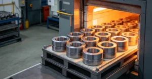
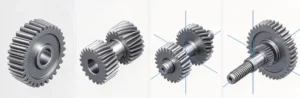
Common types of gears include spur, helical, bevel, worm, hypoid, screw and internal gears. These toothed components transmit motion and torque. Rack-and-pinion mechanisms convert rotation into linear travel, while planetary gear trains combine several gears in one arrangement.
Start with the shaft layout and required motion, then check torque, speed, tooth compatibility and manufacturing requirements.
Compare gear types at a glance
Start with the shaft layout. Parallel shafts, intersecting shafts and offset shafts require different gear geometry. A 90° shaft angle alone is insufficient: bevel shafts intersect, while the axes of a conventional right-angle worm or hypoid pair do not.
| Gear or arrangement | Layout and main selection consideration |
|---|---|
| Spur | Parallel shafts; straight teeth and a relatively simple geometry. |
| Helical | Usually parallel shafts; gradual engagement, with axial thrust to accommodate. |
| Double helical / herringbone | Parallel shafts; opposing helices balance axial thrust under the intended load distribution. |
| Internal | Teeth inside a ring; a mating external pinion permits a compact layout. |
| Bevel | Intersecting shafts; straight or curved teeth on conical pitch surfaces. |
| Hypoid | Offset, nonintersecting shafts; resembles spiral bevel gearing but uses different geometry. |
| Worm and worm wheel | Usually right-angle, nonintersecting shafts; compact reduction with substantial sliding contact. |
| Screw / crossed helical | Nonparallel, nonintersecting shafts; localized contact limits load capacity. |
| Rack and pinion | Rotary-to-linear conversion; straight or helical tooth forms. |
| Planetary gear train | Sun, planets and usually an internal ring; ratio depends on which members are driven, held or used as output. |

Comparing different kinds of gears for parallel shafts
Spur gears
Spur gears have straight teeth parallel to the shaft axis. A conventional external spur pair turns in opposite directions and provides a fixed speed ratio set by tooth count.
Their geometry makes them a useful starting point for simple reducers, mechanisms and gear pumps. Tooth engagement can create more noise than a comparable helical design, particularly as speed increases. Noise also depends on gear accuracy, mounting and lubrication.
Helical gears
Helical teeth run at an angle to the shaft axis. Engagement progresses across the face, which can reduce noise and vibration relative to a similar spur pair.
For a conventional external pair on parallel shafts, the gears have opposite helix hands and the same helix angle. Their tooth system must also match. Helical engagement generates axial thrust, so bearing selection and shaft support are part of the design.
Helical gears are used in automotive transmissions and industrial gearboxes where smoother operation justifies the additional bearing requirements.
Double helical and herringbone gears
These designs combine left-hand and right-hand helices. When both halves share the load as designed, their axial thrust components balance.
Double helical gears commonly have a central relief gap; herringbone teeth meet in a continuous V. Terminology can vary, so identify the required geometry on the drawing. The two forms require more complex manufacturing than a single helical gear.
Internal gears
An internal gear has teeth on the inside of a ring and meshes with an external pinion. With both axes fixed, the ring and pinion rotate in the same direction.
Internal gears are used in planetary drives and other compact mechanisms. Their tooth counts and geometry must be checked for interference. Selecting the same module alone does not establish that a proposed internal pair will assemble and mesh correctly.
Bevel gears for intersecting shafts
Bevel gears transmit motion between intersecting shafts. Their pitch surfaces are conical, and the shaft angle is often 90°, although other angles are possible.
Straight bevel gears have straight teeth. Spiral bevel gears have curved teeth that engage progressively, supporting smoother operation. Zerol bevel gears use curved teeth with a nominal zero mean spiral angle.
A miter gear pair is an equal-tooth-count bevel pair with a 1:1 ratio. It changes the transmission direction while retaining the same speed magnitude.
Typical uses include right-angle machine drives and differential mechanisms. Treat the pair as a coordinated design: mounting distance, shaft angle and tooth contact matter alongside individual gear dimensions.
Offset-shaft options: Worm, hypoid and screw gears
Worm and worm wheel
A worm drive pairs a screw-like worm with a toothed wheel, usually on nonintersecting shafts at 90°. It can provide a large reduction in a compact stage, as in conveyor reducers and tuning mechanisms.
Sliding contact makes lubrication, heat generation and efficiency important selection factors. Performance depends on the geometry, materials, speed, load and assembly conditions; one efficiency figure cannot represent every worm drive.
Self-locking is conditional. A worm wheel’s ability to back-drive the worm depends on factors including lead angle and friction. Where the load must be held against reverse motion, specify an additional holding or braking mechanism.
Hypoid gears
Hypoid gearing resembles spiral bevel gearing, but its shaft axes are offset and do not intersect. This permits layouts such as offset final drives in vehicle axles.
The offset introduces sliding behavior that must be addressed through the tooth design, material pairing and lubrication.
Screw gears
Screw gears, also called crossed helical gears, connect nonparallel, nonintersecting shafts. Their helix angles and hands are selected for the required shaft arrangement.
Compared with conventional parallel-axis helical gearing, contact is localized and load capacity is more limited. They suit relatively light-duty motion transmission where the shaft layout is useful. Do not apply the parallel-shaft rule of opposite helix hands to every crossed-helical arrangement.
Rack-and-pinion mechanisms and planetary gear trains
Gear terminology covers tooth forms, individual gears and types of gear trains. The following names describe complete mechanisms or assemblies.
Rack and pinion
A rack is a straight toothed member that engages a rotating pinion. Rotation produces linear displacement, or linear movement can drive rotation. Racks can use straight or helical teeth.
A steering rack and a machine positioning axis are practical examples of gear applications that require linear travel. Selection also involves rack support, pinion mounting, backlash and travel length.
Planetary gearing
A typical planetary set contains a central sun gear, planet gears on a carrier and an internal ring gear. The planet axes move with the carrier.
The resulting ratio depends on the driven member, output member and any held member. A ring gear does not have to remain stationary in every planetary system. Spur or helical teeth can be used, so planetary gearing is an arrangement rather than a separate tooth profile.
How to choose mechanical gears for an application
Once the shaft layout is fixed, compare the remaining requirements in this order:
- Load and duty: define input speed, transmitted torque, operating hours, starts and reversals. A speed ratio alone does not establish tooth strength.
- Noise and support: compare the engagement behavior, then account for bearing loads and housing stiffness. Helical smoothness comes with axial thrust to manage.
- Positioning: define allowable lost motion on reversal, required backlash and the conditions under which it is checked.
- Environment and production: select material, heat treatment and lubrication for the operating conditions. Compare a suitable stock pair with a custom design before committing to special tooling.
Use manufacturer ratings or a suitable design calculation for the actual duty. A catalog rating based on different speed, service life or loading assumptions should not be treated as the capacity of your assembly.
Check mating compatibility before ordering gears
When comparing types of gears, confirm that the proposed pair can mesh in the available assembly.
For a conventional involute spur pair, check the module or diametral pitch, pressure angle, tooth counts and specified center distance. For helical gearing, also identify the normal or transverse specification system, helix angle and hand.
Backlash is the clearance between mating tooth flanks. Define the required value and assembly conditions where it affects positioning or reversal. Root clearance is the gap between a tooth tip and the mating tooth root; it is a separate requirement.
Worked example: An unshifted external spur pair
Consider this hypothetical example, with a 20-tooth input pinion driving a 60-tooth output gear:
- Both gears use module m = 2 mm and a 20° reference pressure angle.
- Both have standard, unshifted involute geometry.
- The input speed is 1,500 rpm.
For this pair, reference diameter d = m × z, where z is tooth count:
| Quantity | Calculation and result |
|---|---|
| Pinion reference diameter | 2 × 20 = 40 mm |
| Gear reference diameter | 2 × 60 = 120 mm |
| Reference center distance | (40 + 120) / 2 = 80 mm |
| Reduction ratio, input speed / output speed | 60 / 20 = 3:1 |
| Output speed magnitude | 1,500 / 3 = 500 rpm |

Hypothetical pitch-circle schematic. Teeth are omitted; the circles represent reference diameters.
The external gears rotate in opposite directions. These calculations establish basic geometry and kinematics; they do not establish load capacity, acceptable noise or service life.
Use reference diameters, rather than outside diameters, in the center-distance calculation. Profile-shifted designs can use a different working center distance. Helical, bevel, worm and planetary calculations require their own applicable geometry and constraints.
Preparing drawings for a machining quote?
Send the part drawing and CAD model. State whether you need a gear blank, a finished toothed component or a related shaft or housing. Include the mating-part specification when tooth compatibility is part of the request.
Specify the manufactured part and its acceptance requirements
Separate the blank from finished teeth
A gear blank is the body prepared for tooth cutting. Its bore, hub, faces and outside features may involve turning or milling. Finished teeth may require hobbing, shaping, power skiving, tooth milling or grinding, depending on the geometry and specification.
Specify whether the quote covers the blank or a finished gear, including the required heat treatment and inspection. Confirm specialty tooth processing and gear inspection against the drawing during quotation.
For related shafts, hubs and housings, see our CNC machining services.
Define tooth accuracy and mounting geometry separately
For cylindrical involute gears, ISO 1328-1:2013 provides a tooth-flank tolerance classification system. A flank tolerance class does not replace the separate requirements for the bore, locating faces, hub or keyway.
Identify the applicable standard, edition, class and inspection characteristics. Avoid a bare note such as “precision gear” or an unexplained grade number.
Show the required relationships between mounting features on the drawing. Our guide to geometric tolerancing symbols explains the relevant symbols.
For gearbox housings, our bearing housing bore tolerance guide explains how to specify the bearing seats.
Include these inputs in the RFQ
- Part drawing, CAD model, revision and quantity.
- Gear family, tooth count, module or diametral pitch, pressure angle and applicable tooth modifications.
- Helix angle and hand, shaft angle or other geometry needed for the selected family.
- Material grade, heat treatment, hardness and required final condition.
- Bore and mounting requirements, tooth accuracy specification and inspection records.
- Mating-part details and specified assembly conditions where relevant.
Select materials and heat treatment for the actual duty. Heat treatment can affect dimensional accuracy, so specify which requirements apply to the delivered condition.
FAQ
what are the 4 types of gears?
Four commonly introduced families are spur, helical, bevel and worm gears. This introductory grouping is not exhaustive; other forms and arrangements serve different shaft layouts and motion requirements.
What information identifies a gear?
Labels such as “mechanic gear” or “engineering gears” do not identify a tooth form. Use the drawing or manufacturer’s part data to confirm the tooth count, pitch system, pressure angle and any helix angle or hand. Include mounting dimensions and mating-part details when sourcing a replacement.
Is the pinion always the driving gear?
No. Pinion normally means the smaller gear in a mating pair. Either member can be the driver, depending on the application. A small pinion driving a larger gear reduces output speed; reversing the power flow changes that relationship.
Which gear type has the least backlash?
Backlash depends on tooth geometry, manufacturing variation, mounting and any adjustment or preload mechanism. It cannot be selected from the gear-family name alone. Specify the required backlash and test conditions, and review the proposed assembly against that requirement.
Request a quote for gear-related machined parts
Compare types of gears by shaft layout and required motion, then define tooth compatibility, material and acceptance criteria. Complete drawings make the machining scope clear.
Request a machining quote from Baosheng with your CAD model, controlled drawing and quantity. State the required delivery condition and inspection reports. Identify tooth-processing or heat-treatment requirements so they can be assessed in the quotation.